If you have read the HowStuffWorks clause onBoolean logic , then you experience that digital devices depend on Boolean gates . You also know from that article that one way to implement gates involvesrelays . However , no moderncomputeruses relays – it use " chips . "
What if you want to experiment with Boolean Bill Gates and chip ? What if you would wish to build your own digital devices ? It wrick out that it is not that unmanageable . In this clause , you will see how you may try out with all of the gates discussed in theBoolean logic article . We will talk about where you may get office , how you may wire them together , and how you may see what they are doing . In the process , you will start the door to a whole new universe of discourse of technology .
Setting the Stage
In the articleHow Boolean Logic Works , we looked at seven fundamental gate . These gates are the building block of all digital devices . We also saw how to combine these gate together into higher - level role , such as full adders . If you would like to try out with these gate so you could essay things out yourself , the easiest way to do it is to purchase something calledTTL chipsand quickly conducting wire circuits together on a twist called asolderless bread board . lease ’s mouth a little act about the applied science and the process so you may actually try it out !
If you front back at the history of computer engineering , you get that all computers are designed around Boolean gates . The technologies used to enforce those gates , however , have changed dramatically over the years . The very first electronic gates were created usingrelays . These Bill Gates were slow and bulky . Vacuum tubesreplaced relays . Tubes were much quicker but they were just as bulky , and they were also plagued by the problem that tubes cut out ( like light bulbs ) . Oncetransistorswere perfect ( junction transistor were fabricate in 1947 ) , computers start using gates made fromdiscrete transistors . Transistors had many advantages : high reliability , downhearted mightiness consumption and small size of it compared to tube or relay . These transistors were discrete devices , mean that each transistor was a disjoined gimmick . Each one came in a slight metal can about the size of a pea with three wires attached to it . It might take three or four transistors and several resistor anddiodesto create a logic gate .
In the other sixties , integrated circuits(ICs ) were invented . Transistors , resistors and diodes could be construct together on atomic number 14 " chips . " This discovery gave rise to SSI ( small exfoliation integration ) Intelligence Community . AnSSI ICtypically consists of a 3 - mm - square crisp of silicon on which perhaps 20 transistors and various other component have been etched . A distinctive microprocessor chip might hold four or six case-by-case gate . These chips shrank the size of data processor by a factor of about 100 and made them much well-fixed to build .

As poker chip manufacture techniques improved , more and more electronic transistor could be etched onto a single chip . This take to MSI ( intermediate graduated table integration ) chips containing simple components , such as full adders , made up of multiple gate . Then LSI ( large scale consolidation ) allow intriguer to jibe all of the components of a simplemicroprocessoronto a single microprocessor chip . The8080 processor , eject by Intel in 1974 , was the first commercially successful undivided - microprocessor chip microprocessor . It was an LSI check that contained 4,800 transistors . VLSI ( very declamatory scale integration ) has steadily increased the figure of transistors ever since . The first Pentium processor was eject in 1993 with 3.2 million transistors , and current chips can contain up to 20 million transistors .
In society to experiment with gates , we are going to go back in time a bit and utilize SSI ICs . These chips are still widely uncommitted and are extremely dependable and inexpensive . you could build anything you desire with them , one gate at a time . The specific ICs we will use are of a family calledTTL(Transistor Transistor Logic , named for the specific wiring of Bill Gates on the IC ) . The french fries we will use are from the most common TTL series , ring the7400 series . There are perhaps 100 different SSI and MSI buffalo chip in the serial , ranging from simple AND gate up to complete ALUs ( arithmetic logic units ) .
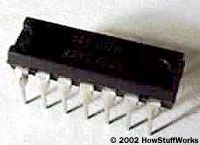
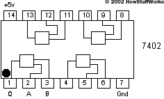
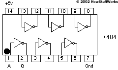
The 7400 - serial chips are housed in DIPs ( dual inline packages ) . As pictured on the right , aDIPis a small plastic package with 14 , 16 , 20 or 24 small metallic element leads protruding from it to provide connections to the gates inside . The well-fixed direction to construct something from these Bill Gates is to set the chips on a solderless bread board . The breadboard permit you wire things together simply by punch opus of telegram into connection holes on the board .
All electronic gate need a informant of electrical mogul . TTL gates use5 voltsfor functioning . The fleck are fairly special about this voltage , so we will want to habituate a unclouded , regulated 5 - V power supply whenever work with TTL chips . Certain other chip families , such as the 4000 serial of CMOS cow dung , are far less particular about the emf they use . CMOS chips have the extra advantage that they use much less power . However , they are very sensible to electrostatic electricity , and that makes them less true unless you have a static - free environment to work in . Therefore , we will stick with TTL here .
Assembling Your Equipment
to meet with TTL gates , you must have several piece of equipment . Here ’s a list of what you will need to buy :
These part together might cost between $ 40 and $ 60 or so , reckon on where you get them .
Let ’s walk through a few details on these portion to make you more familiar with them :
This equipment is not the kind of clobber you are go to witness at the corner memory board . However , it is not unvoiced to find these parts . You have a few choices when essay to buy the components list above :
Notes
The Power Supply
You will by all odds want aregulated 5 - V king supplyto work with TTL chips . As mentioned previously , neither Radio Shack nor Jameco seem to offer a criterion , inexpensive 5 - V mold power supply . One option you have is to bribe from Jameco something like part number 116089 . This is a 5 - volt great power provision from an older Atari television plot . If you expect in the Jameco catalog , you will find that they have about 20 differentsurplus power supplieslike this , grow all sorts ofvoltages and amperage . You need5 voltsatat least 0.3 amps(300 milliamps ) – you postulate no more than 2 amps , so do not buy more world power provision than you demand . What you may do is bribe the power supply , then snub off the connecter and get access to the 5 - volt and ground wires . That will mold very well , and is probably the well-off path . you may use your V metre ( see below ) to check that the power supply develop the potential you postulate .
Your alternative is to construct a 5 - V supply from a littlepower - regular hexahedron transformer . What you require is a transformer that produces7 to 12 DC voltsat100 milliamps or more . observe that :
You may have an previous one lie around that you’re able to expend – read the imprint on the cover and verify it fill all three demand . If not , you could purchase a transformer from Radio Shack or Jameco .
Radio Shack sells a 9 - volt 300 - milliamp transformer ( part number 273 - 1455 ) . Jameco has a 7.5 - volt 300 - milliamp model ( part turn 149964 ) . cut short the connector off the transformer and separate the two wires . Strip about a centimetre of insulation off both wires . Now plug the transformer in ( once it is plugged in , NEVER countenance the two conducting wire from the transformer touch one another or you are potential to burn out the transformer and ruin it ) . Use your volt meter ( see below ) to measure the voltage . You want to check that that the transformer is bring forth approximately the stated voltage ( it may be high by as much as a gene of two – that is okay ) . Your transformer is acting like abatteryfor you , so you also want to determine which telegram is the negative and which is the positively charged . sneak the black and red leads of the volt beat up to the transformer ’s telegram randomly and see if the voltage valuate is plus or negative . If it is electronegative , reverse the leads . Now you know that the conducting wire to which the black lead is attached is the negative ( ground ) wire , while the other is the positive wire .
Building the Regulator
To work up the regulator , you need three section :
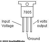
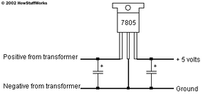
The 7805 takes in a voltage between 7 and 30 volts and regulates it down to on the nose 5 V . The firstcapacitortakes out any ripple coming from the transformer so that the 7805 is receiving a suave stimulation voltage , and the 2d capacitor act as as a load balancer to assure uniform output from the 7805 .
The 7805 has three lead . If you look at the 7805 from the front ( the side with printing on it ) , the three tip are , from left to right , stimulant voltage(7 to 30 volts),ground , andoutput voltage(5 volts ) .
The two capacitance are represented by parallel line . The " + " sign indicates that electrolytic capacitors arepolarized : There is a positive and a negative pole on an electrolytic capacitor ( one of which will be mark ) . You need to make certain you get the sign flop when you deploy the capacitance .
You canbuild this regulator on your breadboard . To do this , you need to understand how a breadboard is internally wire .
On the outer edges of the breadboard are two lines of terminal draw the distance of the plank . All of these terminals are internally connected . Typically , you run +5 volts down one of them and ground down the other . Down the center of the board is a channel . On either side of the channel are sets offive interconnected terminals . you’re able to use your volt - Georg Simon Ohm meter to see the interconnection . fix the metre ’s telephone dial to its ohm place setting , and then hold fast wire at dissimilar points in the breadboard ( the mental testing extend for the time are in all likelihood too thick to fit in the breadboard ’s hole ) .
In the ohm setting , the meter measuresresistance . Resistance will bezeroif there is a connection between two points ( tint the leads together to see this ) , andinfiniteif there is no connective ( hold the leads apart to see this ) . You will obtain that point on the board really are interconnected as shown in the diagram . Another means to see the association is to pull back the stumper on the back of the breadboard a snatch and see the metal connecter .
Now connect the part for yourregulator :
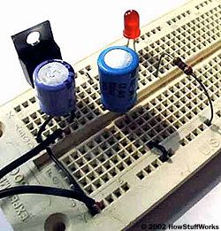
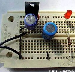
You have create your regulator . It might look like this when you are done ( two views ):
In both of the frame , the lines from the transformer come in from the left field . you could see the ground bloodline of the transformer get in touch directly into the ground strip running the length of the card at the bottom . The top strip provide +5 volts and is connected directly to the +5 pin of the 7805 . The left capacitance permeate the transformer voltage , while the right capacitor filter out the +5 volts produced by the 7805 . The light-emitting diode connects between the +5 and ground strip , through the resistor , and countenance you do it when the power supply is " on . "
plug away in the transformer and measure the input and output voltage of the 7805 . You should see exactly 5 V make out out of the 7805 , and whatever voltage your transformer delivers going in . If you do not , then right away disconnect the transformer and do the following :
Once you see 5 V coming out of the regulator , you could examine it further and see that it is on by connect an LED to it . You need to tie in an LED and a resistorin series– something that is easy to do on your breadboard . You must use the resistor or the LED will burn off out right away . A serious value for the resistor is 330 Georg Simon Ohm , although anything between 200 and 500 ohms will work okay . LED , being rectifying tube , have a polarity , so if your light-emitting diode does not illumine , try out turn back the leads and see if that helps .
It might seem like we ’ve had to go to a tremendous amount of trouble just to get the power supplying wired up and working . But you ’ve find out a duo of things in the process . Now we can try out with Boolean gates !
Playing with Boolean Gates
If you used the mesa on the previous page to order your parts , you should have six dissimilar chips containing six different types of gate :
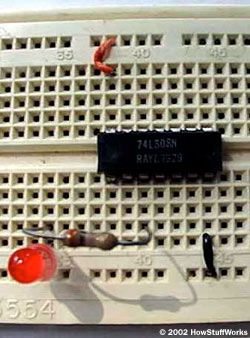
Let ’s start with a7408 AND chip . If you look at the micro chip , there will normally be a dot at pin 1 , or an roughness at the pin 1 goal of the buffalo chip , or some other marking to suggest pin 1 . agitate the chip into the breadboard so it straddles the center epithelial duct . you could see from the diagram that on all chips , pin 7 must connect to ground and stick 14 must plug into to +5 volts . So join those two pivot appropriately . ( If you connect them backward you will burn the chip out , so do n’t connect them backward . If you happen to burn a chip out accidentally , throw it aside so you do not confuse it with your good parts . ) Now connect an LED and resistor between stick 3 of the chip and ground . The light-emitting diode should light . If not , override the LED so it lights . Your National Intelligence Community should look like this :
Here is what is happen . In TTL , +5 represents a binary " 1 " and land represents a binary " 0 . " If an input pin to a gate is not connected to anything , it " floats high , " intend the logic gate pretend an assumption that there is a 1 on the pin . So the AND gate should be envision 1 on both the A and Bel inputs , mean that the production at pin 3 is give up 5 volts . So the light-emitting diode lights . If you crunch either pin 1 or 2 or both on the chip , the LED will extinguish . This is the standard behavior for an AND logic gate , as described inHow Boolean Logic Works .
prove out the other gates by connecting them on your breadboard and see that they all behave accord to the logic tables in theBoolean logicarticle . Then try wire up something more complicated . For illustration , wire up theXOR gate , or theQ bit of the full adder , and see that they act as expected .
Build It!
In hypothesis , you now have the fundamental knowledge you need to build any digital machine . you’re able to take the basic gates discussed in this article and build anything . However , it is often more convenient to use tumid - scale devices so that you do n’t have to fuse 50 fries to build something vernacular like anALU . It is also helpful to see example of dissimilar means to aggregate gates to create complicated systems .
If you would like to put to work on a bigger project , you’re able to try building the digital clock described inHow Digital Clocks Work . If you need to learn more about TTL devices , the following books will be helpful :
You will be AMAZED at what you’re able to create with just a few United States Intelligence Community and some creativity . Have fun with it !
For more information on electronic gates and related topic , check out the links on the next page .
